An innovative testing set-up was developed in order to perform quasi-static out-of-plane tests of full-scale IM walls with airbags which was lately upgraded with pneumatic actuators. Both tests setups were described and discussed throughout the manuscript.
PROBLEM
Quasi-static Cyclic Out-of-plane tests presents high level of difficulties due to the setups complexities and since it is necessary sufficient capacity and lab facilities to test full-scale specimens.
AIM AND SCOPE
The main goal of the present manuscript is to present experimental campaign regarding the quasi-static cyclic out-of-plane tests of full-scale IM walls, detailled discussion of the test setup concept and recent upgrade the main lessons and future works.
DESIGN AND CONSTRUCTION OF THE TEST SPECIMENS:
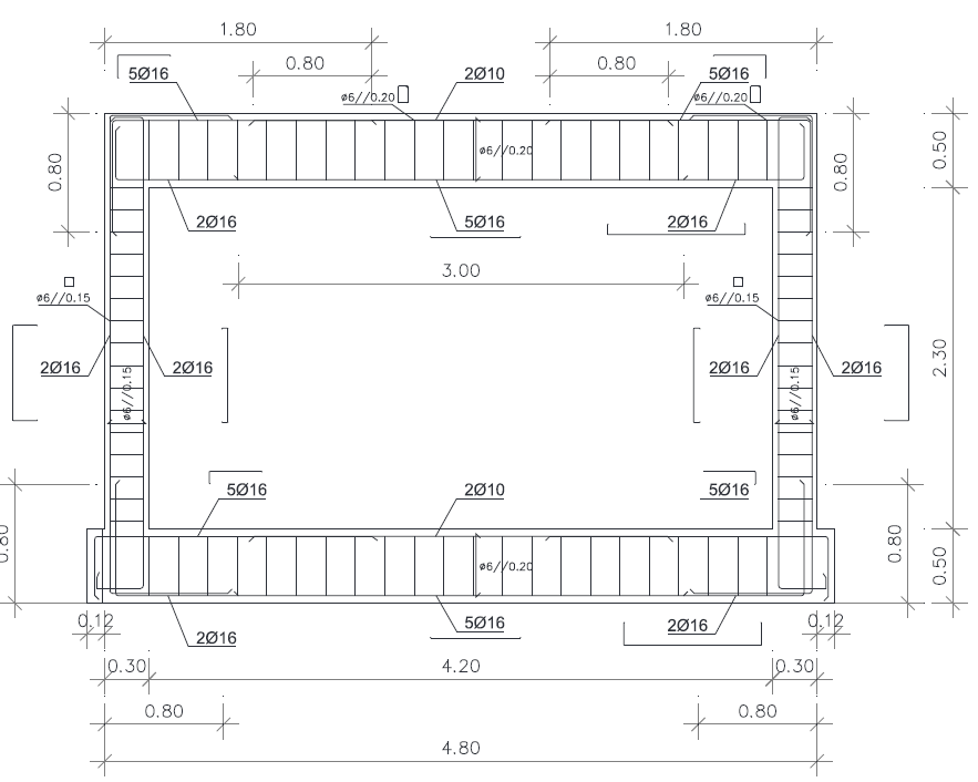
The specimen dimensions found are 4.80 m width and 3.30 m height, with the columns sections 0.30 x 0.30 m2 and the top and bottom beams 0.30 x 0.50 m2. Grades of C20/25 and A500 were adopted for concrete and reinforcing steel, respectively. The mortar adopted was a typical M5 class. No plaster was adopted
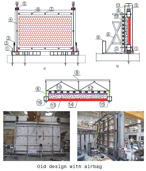
Old system: The out-of-plane test consisted of the application of a uniformly distributed surface load through a system composed of seven nylon airbags, reacting against a self-equilibrated steel structure. Twelve steel threaded rods, crossing the RC elements in previously drilled holes, were used to equilibrate the reaction force resulting from the pressure applied by the airbags in the infill panel. In each column, the axial load was applied by means of a hydraulic jack inserted between a steel cap.
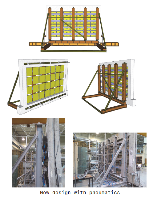
New system: The concept was based on the previous one with airbags which consists on the application of a distributed out-of-plane loading through 28 pneumatic actuators that mobilize all the infill panel surface since it is placed between them a wood plate with dimensions 0.5 x 0.5 m. The pneumatic actuators are linked to four horizontal HEB140 steel profiles that reacted against 5 vertical alignments HEB200.
The specimens tested had the following characteristics:
------------------------------------------------------------------
| Specimen | Previous in-plane | Axial | Type of | Panel |
| | damage (%) | load (kN) | test | support |
|----------|-------------------|-----------|-----------|---------|
| Inf_01 | 0.0 | 270 | Monotonic | Full |
| Inf_02 | 0.0 | 0 | Cyclic | Full |
| Inf_03 | 0.5 | 0 | Cyclic | Full |
| Inf_04 | 0.0 | 270 | Cyclic | Full |
| Inf_05 | 0.0 | 0 | 2/3 width | Full |
------------------------------------------------------------------
CONCLUSIONS
From the results, it was observed a significant difference between the test results, with and without previous in-plane damage, namely:
a) the maximum strength was almost four times higher for the tests without previous in-plane damage and for higher out-of-plane drift values;
b) a significant reduction in the initial stiffness was observed in the test with previous in-plane damage when compared with the others;
c) a significant maximum strength reduction was found in the tests without the previous in-plane damage, which was not verified in Inf_03.
The failure modes observed in each of the tests reveal a different out-of-plane behaviour of the IM walls with and without previous in-plane damage. The tests on specimens without previous damage showed vertical cracking, with detachment between the infill panel and the surrounding RC frame in the top and bottom joints. A trilinear cracking was observed with deformation concentrated in the middle point of the wall, with slight cracking in the top joint to specimens subjected to cyclic tests without axial load on the top of the columns and previous in-plane damage. For the test with previous in-plane damage, detachment was observed between the infill panel and the surrounding top beam and columns, and typical rigid body behaviour was found.
Regarding the influence of the axial on the columns prior to carrying out the tests for out-of-plane, revealed a decrease of the out-of-plane stiffness of the panel although combined with an increase in load bearing capacity of the same panels. This increase of the confinement, resulted in a different failure mode when compared with the tests without axial load in the columns. The application the axial load on the top of the columns, without increasing the same during the test leads to the panel acquire a markedly brittle failure. The definition of the stiffness degradation curve, allows to visualize that such non-structural elements begins to lose rigidity to share out-of-plane when the request starts to be transmitted to the panels. This loss of stiffness will be more or less accentuated depending on the behavior exhibited by the panel, that is, the case presents a slow and gradual failure or an instantaneous rupture/collapse.
RECOMMENDATIONS FOR FUTURE RESEARCH
None were specified.